SolidWorks is a solid modeling computer-aided design (CAD) and computer-aided engineering (CAE) computer software application. SolidWorks was developed by Dassault Systèmes. SolidWorks Corporation was founded in December 1993 by Massachusetts Institute of Technology graduate Jon Hirschtick.
Jon Hirschtick used $1 million to set up the company. Initially based in Waltham, Massachusetts, United States, Hirschtick recruited a team of engineers with the goal of building 3D CAD software that was simple, easy-to-use for all engineers and designers, affordable, and available on the Windows desktop. SolidWorks released its first product as SolidWorks 95, in November 1995.
SolidWorks currently markets several versions of the SolidWorks CAD software and upgrade with more amazing modules in addition to the eDrawings, a collaboration tool, and DraftSight, a 2D CAD product. Over more than 2.5 million engineers and designers at more than 190,000 companies are using SolidWorks as of 2016.
SolidWorks currently markets several versions of the SolidWorks CAD software in addition to eDrawings, a collaboration tool, Visualization, and DraftSight, a 2D CAD product. SolidWorks is a solid modeler, and utilizes a parametric feature-based approach which was initially developed by PTC to create models and assemblies. The software is written on Parasolid-kernel.
Design in SOLIDWORKS:
SolidWorks is structured in three main types are, Part, Assembly and Drawing. Part modeling is a 3D representation of a single design component. Assembly is a 3D arrangement of parts and/or other assemblies. Drawing is a 2D engineering drawing, typically of a part or assembly.
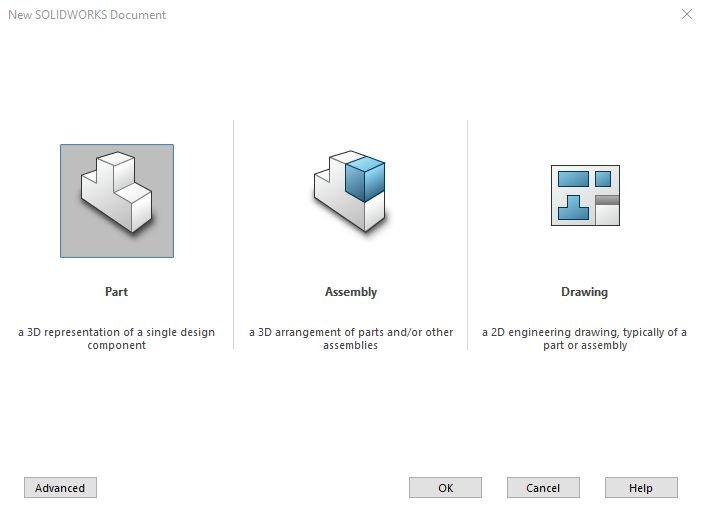
Part Modeling: The part modeling is the first and one of the most important mode of SolidWorks in which a 3D model is created. To create a 3D model, you need to make a 2D sketch from sketching environment and make it into 3D part model with the help of 3D features as per your requirement. The sketch is created with the help of three default planes which are Front Plane, Top Plane and Right Plane.
Assembly: In assembly, you can make your part models together into a single assembly as per the product requirement. Assembly can create by mating relations between parts. In assembly, the 3D model is use to make a complete product by mating its relations by requirement of a developing product. Assembly is also using three default planes to make a 3D parts assemble in an assembly of product.
Drawing: In drawing, a creation of 2D engineering drawing typically of a part of an assembly. You can create a 2D engineering drawing with the help of 3D model or an assembly and gives it require annotations and fill with notations require for manufacturing of designed product. In drawing, you can also make a bill of material, show a 3D isometric representation of a 3D part model.
Also Read: Best Mechanical Engineering Software’s
Modules in SOLIDWORKS:
The basic module in the SolidWorks window are Part, Assembly and Drawing.
2D CAD: The perfect 2D CAD with world class drafting experience by SolidWorks.
3D CAD: SolidWorks 3D CAD solutions helps engineers and designing team to quickly transform new ideas into great designs and products.
CAM: SolidWorks CAM solutions helps design and production team to get from design to manufacturing quickly with an integrated process.
SIMULATION: SolidWorks Simulation solutions helps engineers and designers to quickly transform new ideas into great products by simulating and analysis of the design.
ELECTRICAL DESIGN: SolidWorks Electrical Design solutions helps engineers to quickly transform new ideas into great products by integrating ECAD with MCAD.
PRODUCT DATA MANAGEMENT: SolidWorks PDM solutions helps designers and management team to quickly transform new ideas into great products by managing data files and other product data documentations.
File Format in SolidWorks:
SolidWorks files use the Microsoft Structured Storage file format. This files are embedded within each .SLDRW which are drawing files, .SLDPRT which are part files, .SLDASM which are assembly files including preview bitmaps and metadata sub-files. SolidWorks also allows part files to save as information into files formats such as .STEP, .IGS, .STL and many more, which let the model be display and modify in other formats .