To become a perfect in the art of engineering drawing, then you should learn and need to become perfect in dimensioning. In this article, we will learn about dimensioning and types of dimensioning systems used in engineering drawing.
What is Dimensioning?
Dimensioning is the process of measuring the area or the volume of an object that occupies. Dimensions are a numerical value expressed in appropriate units of measurements and which are used to define the size, location, weight, orientation of an object.
Dimensioning plays one of the most important role in engineering and design documentation as it provides all required information for manufacturing, construction, and other applications. Dimensioning is the process of specifying the size and location of objects, features, or components on a technical engineering drawing.
While designing or constructing any object or a product, its size and shape must be known, an engineering drawing is a representation of every essential details with proper dimensions and annotations. The dimensions must indicate the sizes and required details of an object or product.
Order of Dimensioning:
After completion of an engineering drawing, the following order is important to kept in mind are as,
- Drawing of extension line.
- Drawing of Dimension Line.
- Drawing of arrowheads.
- Writing the numerical value.
- Drawing of the cutting plane line.
- Drawing of the leader line.
- Drawing the centerline.
- Writing of notes and specifications.
Types of Dimensioning:
There are some of the important types of dimensioning are as follows,
- Linear Dimensioning.
- Angular Dimensioning.
- Chain Dimensioning.
- Diametric Dimensioning.
- Radial Dimensioning.
- Ordinate Dimensioning.
- Coordinate Dimensioning.
- Limit Dimensioning and Tolerances.
- Baseline Dimensioning.
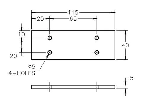
1. Linear Dimensioning:
Linear dimensioning is used to specify the length, width and height of an object. Linear dimensioning involves providing numerical values that measured from one side to another side of an object. It includes dimension lines, arrows, extension lines, etc.
2. Angular Dimensioning:
Angular dimensioning are used to define angles between lines or surfaces. Angular dimensioning provides an information about the inclination of angles, corners, inclination and edges of an object. Angular dimensioning represents in degrees (°) and are indicated with an arc and a value.
3. Chain Dimensioning:
Chain dimensioning are used to specifying a series of interconnected dimensions along a path. Chain Dimensioning is when dimensions are arranged in a straight line in which dimensions are drawn from one feature to a second feature. Chain dimensioning is used when multiple features or objects have a sequential relationship.
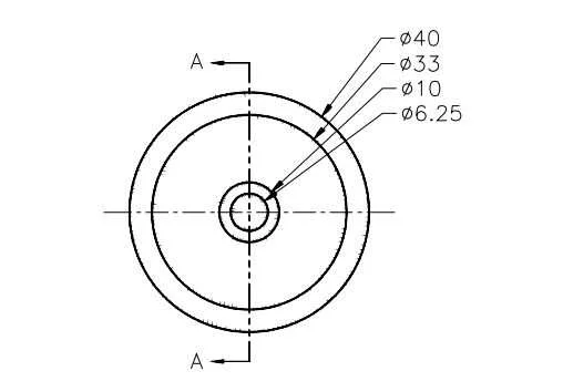
4. Dimetric Dimensioning:
Diametric dimensioning is a type of radial dimensioning in which focuses specifically on indicating the diameter of circular objects, such as holes or cylindrical features on an object. Dimetric dimensioning are used to define the dimeter of an object.
5. Radial Dimensioning:
Radial dimensioning is used for circular or curved features, such as arcs or circles. Radial Dimensioning can place the dimension lines and measurements either inside or outside of the circle/arc. It specifies the radius or diameter of circular objects and provides insight into the size and curvature of these elements.
6. Ordinate Dimensioning:
Ordinate dimensioning specifies a baseline or reference line to indicate the positions of features along a single axis of an object. Ordinate dimensioning is used when the X and the Y coordinates, from one location, are the only dimensions necessary. It is used to reduce the number of dimensions shown on an engineering drawing.
7. Coordinate Dimensioning:
Coordinate dimensioning are used for providing dimensions based on a common reference point or coordinate system of an object. Coordinate dimensioning creates a series of “chained” dimensions having a common origin and single dimension line. It is useful where linear dimensions alone may not fully describe the geometry.
8. Limit Dimensioning and Tolerances:
Limit dimensioning includes upper and lower limits to specify allowable variations in dimensions. The limits are two extreme permissible sizes for a dimension, there being a higher limit and a lower limit. Tolerances is the algebraic difference between the maximum limit and minimum limit of a hole or shaft. Tolerance is the maximum permissible variation in a dimension.
9. Baseline Dimensioning:
Baseline dimensioning is used to align dimensions with a common baseline, simplifying the layout of dimensions and improving clarity. Baseline dimensions are multiple dimensions measured from the same location. Linear and angular dimensions are need to create first before creating baseline dimensions.
All types of dimensioning mentioned specific purpose and choose based on the characteristics and applications.
Principle of Dimensioning:
After completing an engineering drawing, the most important thing in an engineering drawing is to gives proper dimensions and annotations in such as way that they can be easily readable and understandable. Dimensions should be given on a manner that reflects the actual size and shape of an object. Dimensions should not be repeated unless it is necessary in an engineering drawing. Unnecessary dimensions should be avoided.
Dimensions should be clear and unambiguous, leaving no room for interpretation. Dimensions should be placed outside the object whenever possible, to avoid cluttering the object view. Use clear and concise annotations to explain any specific instructions, details, tolerances, or additional information.
By using these principles of dimensioning, engineers and designers can create technical engineering drawings that effectively convey design intent, facilitate accurate manufacturing, and lead to successful assembly and construction processes of an object or a product.
Purpose of Dimensioning:
Dimensioning is one of the most important contexts of technical engineering such as architectural plans, engineering drawings, or mechanical designs, dimensioning serves several purposes are as follows,
Communication with Engineering Drawing: Dimensioning ensures that anyone can understand the size, shape, volume and position of an object.
Accuracy: Accurate dimensions help ensure that the manufactured or constructed object matches the intended design.
Limits, Fits and Tolerances: Dimensioning also specifies tolerances which indicates the allowable variations into the nominal dimensions. Tolerances ensures that an object still function if they are not as the exact size.
Interchangeability: Accurate dimensioning enables the interchangeability of parts of an object, allowing components to fit together seamlessly without adjustments.