Hole:
It is a term used to specify the internal features of parts.
Shaft:
It is a term used to specify the external features of parts.
Size:
It is the numerical value of a linear dimension in a particular unit.
Basic Size:
It is the standard size of a part, with reference to which, all the limits of variations of size are determined.
Actual Size:
It is the measured size of job. The difference between the basic size and the actual size should not exceed a certain limit.
Zero Line:
The line corresponding to basic size is called as zero line. It is the line of zero deviation.
Read Also: Introduction to Metrology
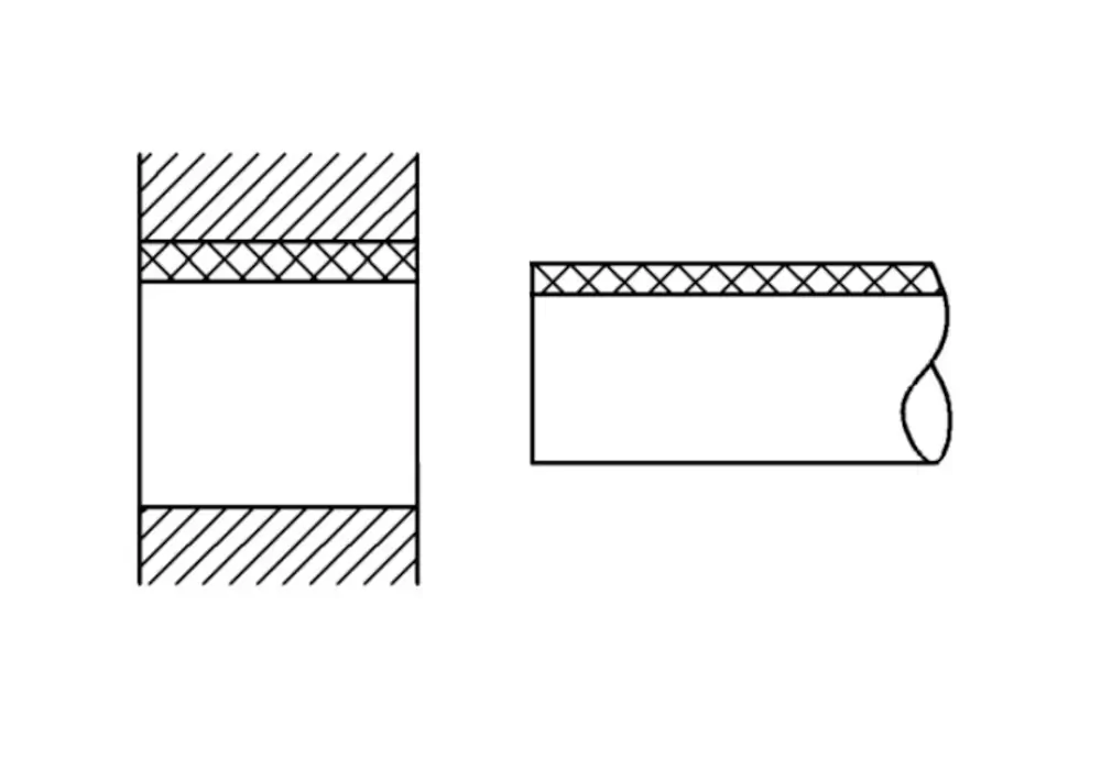
Basic Shaft:
It is the shaft, whose upper deviation is zero or whose maximum limit of size is equal to basic size.
Basic hole:
It is the hole, whose lower deviation is zero or whose minimum limit of size is equal to basic size.
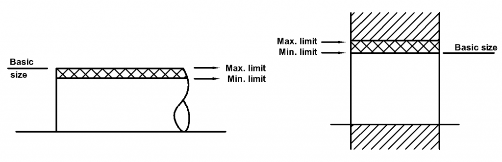
Maximum Limit of Size:
It is the term maximum limit of size referred to the maximum or greatest permissible size of a feature.
Minimum Limit of Size:
It is the term minimum limit of size referred to the minimum or smallest permissible size of a feature.
Deviation:
It is the amount by which the size of a part deviates from its basic size. Hence, it is the algebraic difference between actual size and basic size.
The upper deviation is the algebraic difference between the maximum limit and the basic size.
The lower deviation is the algebraic difference between the minimum limit and the basic size.
The mean deviation is the arithmetical mean between the upper and the lower deviations.
The fundamental deviation is either upper deviation or lower deviation, which is nearest one to the zero line for either hole or a shaft.

Allowance:
Allowance is the prescribed difference between the hole dimension and shaft dimension for any type of fit. It is the intentional difference between the lower limit of the hole and higher limit of the shaft.
An allowance can be either positive or negative according to the type of fit required. If the condition in which, the shaft is smaller than the hole is called positive allowance. And if the shaft is larger than the hole is called negative allowance. The positive allowance is also called as clearance and negative allowance is called as interference.

Limits of Size:
The limits are two extreme permissible sizes for a dimension, there being a higher limit and a lower limit. The greater of these two sizes is called maximum limit or high limit of size, while the smaller size is the minimum limit or low limit of size.

Tolerance:
It is the algebraic difference between the maximum limit and minimum limit of a hole or shaft. Tolerance is the maximum permissible variation in a dimension. It is also defined as the difference between upper and lower deviation and has an absolute value without sign.
Tolerance is of two types, i.e. unilateral and bilateral.
If the tolerance is allowed on one side of the nominal size, the system of tolerance is called as unilateral, i.e. tolerance lies on one side of the basic size upper or below it. Unilateral system is preferred in interchangeable manufactured parts, especially where precision fits are required, because it is easy and simpler to determine deviations.
In this system, the dimension of a part is permitted to vary on both sides of the basic size, i.e. limits of tolerance lie on either side of the basic size; but may not be necessarily equally disposed about it. This system is used in large size manufacture, machine setting.

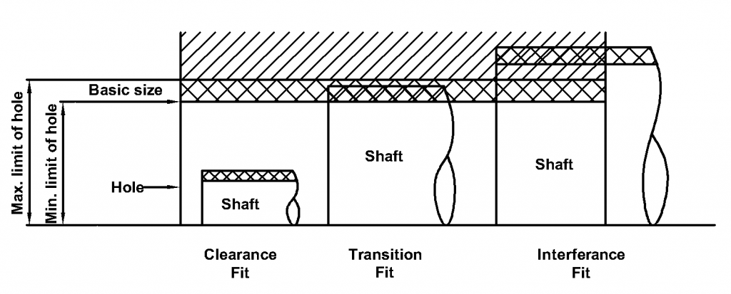
Fits:
The relation between the two parts, where one is inserted into the other with a certain degree of tightness or looseness is known as fit. It is the degree of tightness or looseness between two mating parts to perform a definite function.
Fits can be classified into three main types are as follows,
- Clearance Fit.
- Transition Fit.
- Interference Fit.
1. Clearance Fit:
In this type of fit, the largest permitted shaft diameter is smaller than the diameter of the smallest hole, so that the shaft can rotate or slide through, with different degrees of freedom according to the purpose of the mating parts. In clearance fit, the difference between the maximum size of the hole and minimum size of the shaft is called maximum clearance, whereas the minimum size of the hole and maximum size of the shaft is known as minimum clearance. For examples is Sliding fit, running fit, etc.
2. Transition Fit:
In this type of fit, the size limits of mating parts are so selected that either clearance or interference may occur depending upon the actual size of the parts. In transition fit, the diameter of the largest allowable hole is greater than that of the smallest shaft, but the smallest hole is smaller than the largest shaft, so that small positive or negative allowance between the shaft and hole are employed. The transition fit has different types are Force fit, Push fit, tight fit and ringing fit. For examples is Spigot in mating holes, coupling rings, etc.
3. Interference Fit:
In this type of fit, diameter of minimum allowable shaft is greater than that of maximum allowable hole. In this fit, the shaft and the hole members are intended to be attached permanently, so that they can be used as a solid component, but according to the purpose and function of this combination, this type of fit can be varied. The interference fit has different types are Shrink fit, Heavy drive fit and light drive fit. For examples is Press fit, shrink fit, driving fit, etc.
Hole Basis System:
In this system, the design size of hole, whose lower deviation is zero, is assumed as basic size and different clearances or interferences are obtained by varying the limits of the shaft to have different class of fit. It is very easy, convenient and less costly to make holes of correct sizes.
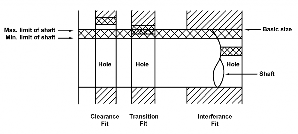
Shaft Basis System:
In this system, the design size of a shaft, whose upper deviation is zero, is assumed as basic size and different clearances or interferences are obtained by varying the limits of the hole to have different class of fit. It is not suitable in mass production and difficult to vary the hole sizes.
Interchangeability:
An interchangeability part is one which can be substituted for similar part manufactured to the same drawing. It is only possible when certain standards are strictly followed in various manufacturing units. Interchangeability reduced the cost of production and increases the rate of production.